- 您现在的位置:买卖IC网 > Sheet目录3822 > PIC18F4525-I/ML (Microchip Technology)IC MCU FLASH 24KX16 44QFN
PIC17C4X
DS30412C-page 108
1996 Microchip Technology Inc.
Table 15-2 lists the instructions recognized by the
MPASM assembler.
All instruction examples use the following format to rep-
resent a hexadecimal number:
0xhh
where h signies a hexadecimal digit.
To represent a binary number:
0000 0100b
where b signies a binary string.
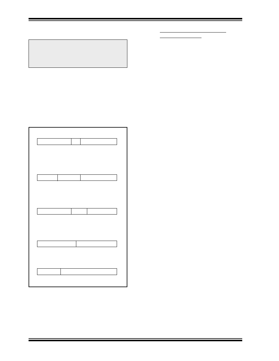
FIGURE 15-1: GENERAL FORMAT FOR
INSTRUCTIONS
Note 1: Any unused opcode is Reserved. Use of
any reserved opcode may cause unex-
pected operation.
Note 2: The shaded instructions are not available
in the PIC17C42
Byte-oriented le register operations
15
9
8
7
0
d = 0 for destination WREG
OPCODE
d
f (FILE #)
d = 1 for destination f
f = 8-bit le register address
Bit-oriented le register operations
15
11 10
8 7
0
OPCODE
b (BIT #)
f (FILE #)
b = 3-bit address
f = 8-bit le register address
Literal and control operations
15
8
7
0
OPCODE
k (literal)
k = 8-bit immediate value
Byte to Byte move operations
15
13 12
8 7
0
OPCODE
p (FILE #)
f (FILE #)
Call and GOTO operations
15
13 12
0
OPCODE
k (literal)
k = 13-bit immediate value
p = peripheral register le address
f = 8-bit le register address
15.1
Special Function Registers as
Source/Destination
The PIC17C4X’s orthogonal instruction set allows read
and write of all le registers, including special function
registers. There are some special situations the user
should be aware of:
15.1.1
ALUSTA AS DESTINATION
If an instruction writes to ALUSTA, the Z, C, DC and OV
bits may be set or cleared as a result of the instruction
and overwrite the original data bits written. For exam-
ple, executing CLRF
ALUSTA
will clear register
ALUSTA, and then set the Z bit leaving 0000 0100b in
the register.
15.1.2
PCL AS SOURCE OR DESTINATION
Read, write or read-modify-write on PCL may have the
following results:
Read PC:
PCH
→ PCLATH; PCL → dest
Write PCL:
PCLATH
→ PCH;
8-bit destination value
→ PCL
Read-Modify-Write:
PCL
→ ALU operand
PCLATH
→ PCH;
8-bit result
→ PCL
Where PCH = program counter high byte (not an
addressable register), PCLATH = Program counter
high holding latch, dest = destination, WREG or f.
15.1.3
BIT MANIPULATION
All bit manipulation instructions are done by rst read-
ing the entire register, operating on the selected bit and
writing the result back (read-modify-write). The user
should keep this in mind when operating on special
function registers, such as ports.
发布紧急采购,3分钟左右您将得到回复。
相关PDF资料
DSPIC30F2023-30I/ML
IC DSPIC MCU/DSP 12K 44QFN
PIC16LF767-I/ML
IC PIC MCU FLASH 8KX14 28QFN
PIC18LF2320-I/SO
IC MCU FLASH 4KX16 EEPROM 28SOIC
PIC18F4458-I/ML
IC PIC MCU FLASH 12KX16 44QFN
DSPIC33FJ64GP706A-I/PT
IC DSPIC MCU/DSP 64K 64-TQFP
PIC16F874-20/P
IC MCU FLASH 4KX14 EE 40DIP
DSPIC33FJ64GP706-I/PT
IC DSPIC MCU/DSP 64K 64TQFP
PIC24HJ128GP210-I/PT
IC PIC MCU FLASH 128KB 100TQFP
相关代理商/技术参数
PIC18F4525-I/P
功能描述:8位微控制器 -MCU 48KB 3968 RAM 36I/O RoHS:否 制造商:Silicon Labs 核心:8051 处理器系列:C8051F39x 数据总线宽度:8 bit 最大时钟频率:50 MHz 程序存储器大小:16 KB 数据 RAM 大小:1 KB 片上 ADC:Yes 工作电源电压:1.8 V to 3.6 V 工作温度范围:- 40 C to + 105 C 封装 / 箱体:QFN-20 安装风格:SMD/SMT
PIC18F4525-I/P
制造商:Microchip Technology Inc 功能描述:IC 8BIT FLASH MCU 18F4525 DIP40
PIC18F4525-I/PT
功能描述:8位微控制器 -MCU 48KB 3968 RAM 36I/O RoHS:否 制造商:Silicon Labs 核心:8051 处理器系列:C8051F39x 数据总线宽度:8 bit 最大时钟频率:50 MHz 程序存储器大小:16 KB 数据 RAM 大小:1 KB 片上 ADC:Yes 工作电源电压:1.8 V to 3.6 V 工作温度范围:- 40 C to + 105 C 封装 / 箱体:QFN-20 安装风格:SMD/SMT
PIC18F4525-I/PT
制造商:Microchip Technology Inc 功能描述:IC 8BIT FLASH MCU 18F4525 TQFP44
PIC18F4525T-I/ML
功能描述:8位微控制器 -MCU 48KB 3968 RAM 36I/O RoHS:否 制造商:Silicon Labs 核心:8051 处理器系列:C8051F39x 数据总线宽度:8 bit 最大时钟频率:50 MHz 程序存储器大小:16 KB 数据 RAM 大小:1 KB 片上 ADC:Yes 工作电源电压:1.8 V to 3.6 V 工作温度范围:- 40 C to + 105 C 封装 / 箱体:QFN-20 安装风格:SMD/SMT
PIC18F4525T-I/PT
功能描述:8位微控制器 -MCU 48KB 3968 RAM 36I/O RoHS:否 制造商:Silicon Labs 核心:8051 处理器系列:C8051F39x 数据总线宽度:8 bit 最大时钟频率:50 MHz 程序存储器大小:16 KB 数据 RAM 大小:1 KB 片上 ADC:Yes 工作电源电压:1.8 V to 3.6 V 工作温度范围:- 40 C to + 105 C 封装 / 箱体:QFN-20 安装风格:SMD/SMT
PIC18F452-BL
制造商:POWERLITE SYSTEMS 功能描述:BOOTLOADER PIC18F452 FOR FLASHLAB 制造商:POWERLITE SYSTEMS 功能描述:BOOTLOADER, PIC18F452, FOR FLASHLAB 制造商:POWERLITE SYSTEMS 功能描述:BOOTLOADER, PIC18F452, FOR FLASHLAB, Silicon Manufacturer:Powerlite Systems, Cor 制造商:POWERLITE SYSTEMS 功能描述:PIC18F452 W/ BOOTLOADER, FOR FLASHLAB, Silicon Manufacturer:Powerlite Systems, Core Architecture:PIC, Core Sub-Architecture:PIC18F, Kit Contents:Board , RoHS Compliant: Yes
PIC18F452-E/L
功能描述:8位微控制器 -MCU 32KB 1536 RAM 34I/O RoHS:否 制造商:Silicon Labs 核心:8051 处理器系列:C8051F39x 数据总线宽度:8 bit 最大时钟频率:50 MHz 程序存储器大小:16 KB 数据 RAM 大小:1 KB 片上 ADC:Yes 工作电源电压:1.8 V to 3.6 V 工作温度范围:- 40 C to + 105 C 封装 / 箱体:QFN-20 安装风格:SMD/SMT